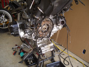
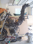
--Lifting the rear frame--
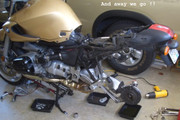
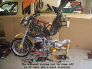
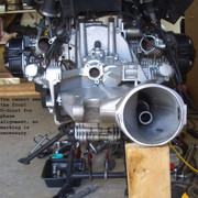
Here is where I started in my garage within the readjusted 6 foot space between Ann's Civic and my Nissan pickup. The far away pics were taken when her car was away. The wheel and exhaust system came off in a flash! Removing the header was no struggle at all after the header nuts were removed and CatBox clamps were loosened up. Easiest when you leave the crossover clamp tight and tap the headers off using multiple soft forward taps on the crossover pipe rear side midpoint with a heavy dead blow plastic mallet. I had some experience removing it for the 3 times I power cleaned and polished the chrome parts to like new looks. Then remove the O2 sensor wire's plug-in (follow the wire) and the CatBox. I used a contrast enhancing big cardboard sheet for my photo studio backdrop after this first pic:
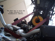
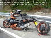
In slowly/incrementally lifting the rear frame by hand and incrementally tightening the top tie-down's slack you'll need a few very important warnings to prevent expen$ive damage. First, note the "top indicator marking" on each asymmetrical airbox tube, then loosen the TB airbox tube's forward and rearward clamps, then rotate/wiggle each one rearward into the airbox, affectively disconnecting them from each TB. Next, remove each fuel injector from each TB, taking care not to stress their bonded on plastic fuel lines and let them hang free. Then roll on each throttle pulley to full throttle with one hand (not easy) and with the other hand rotate the throttle cable slack loop outward to enter the pulley's outer inboard removal slot that allows the cable to pass through with its barrel end attached. Loosen the throttle cable ferrule's locknut, un-thread it completely and remove the cable, letting it hang free out of the way. Finally remove the ground wire on the bottom of each TB housing.
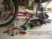
After your break look at the rear frame's top forward mounting bolts that are very close together. One is the pivot point nut that you only loosen on each side, the other is a bolt for for security on each side, which needs to be removed. As soon as you start lifting a tiny amount you'll see what has to be removed in the battery box area, like the battery box! Its substantial what has to be disconnected so nothing will not be stretched or crushed, so be cautious. On the tranny rear, remove the slave unit with hose attached and set it aside.
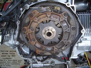
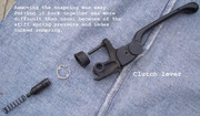
When I removed the clutch slave I was stunned at what I found! Then I took the slave apart. I found a worn out mess and a component total loss. It was well over 3 years ago in Woodstock NY (where the infamous stoner concert was) when the slowly upward rotating left handguard touched the clutch lever ball end and unnoticed by me, held in the clutch lever lightly without the clutch slipping. That long term heavy pressure on the slave piston's tiny throwout bearing overheated it and it must have seized, then spun the slave piston. That friction boiled the DOT4 fluid and my clutch lever went soft as air. I immediately downshifted to neutral without the clutch to a stop for an immediate fix of the handguard and reverse bled the air in the clutch system after a cool-down by cycling the lever while tilted the right ways (rear wheel high, steering full right). When I found the results of the problem it was really disturbing to me:
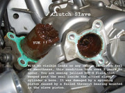
Amazingly when the piston spins and scores the cylinder's bore, the damaged areas are on both sides of and away from the portion where the rubber piston ring travels, so the clutch release still works normally. The slave did weep a little DOT-4, undetected, from the spinning action and that made that jellied mess!! Then I had to pull out the clutch pushrod using needle nosed ViseGrips. You may not need the VGs to pull yours out because mine had damage as described above.
--Removing the SwingArm--
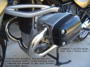
After 35 minutes of heat from both an 1100 degree (593 C) heat gun AND a modestly applied, scanning propane torch flame I had all 4 of the swingarm pivot bolts loosened. The large Aluminum locknuts were very tight! To prevent localized heat expansion stress cracks, the heat was applied to the circumference in about 10 inch scans on the swingarm casting up to but not including the pivot shaft locknuts where stationary and more application time was spent nearest the nuts while progressively decreasing heat application time was spent approaching and leaving the 10" away heating zone was. That effectively, decreasingly fades out the heat affect zone stress area to negate any damage. Thanks to an InfraRed thermometer Bash gift from BoxerMania, I knew when and where the 210 degree temp was reached.
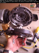
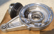
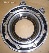
Because of the 61K miles and current level of disassembly I decided it was time to remove the final drive cover to inspect the FD bearings before removing the swingarm, as it served as an excellent and very rigid support. Because the rear FD boot slips off (and carefully back on) the boot's (Larger diameter) front mounting groove portion, re-using the biggest original ziptie was almost too easy. You can use that same non destructive boot remove/replace procedure for oil seal leak checks. Just start at the bottom, grip tightly and stretch squeeze the slack portion up-n-over the groove's missing ridge at the top. When you see the groove's shape, it'll be clear what you need to do (hopefully).
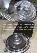
Surprisingly, the cover pressed off the shaft without heat and with a balanced downward push on the cover by hand against the wheel stud's heads on the cement:
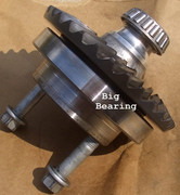
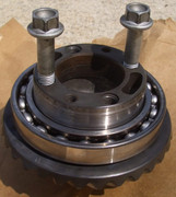
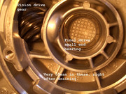
I did not see any damaged bearings other than the big bearing's degreased and ambient air dried freeplay. With gear oil remaining on it after an overnite drain, it was tight and quiet. Changing my gear oil from 75-90 Mobil-1 to an 85W-140 synthetic blend I had on hand dramatically reduced the noises and all but eliminated the straight ahead instability. Resetting both ParaLever pivot pin zero play adjustments also helped too. It'll be ride some more, wait and see from here and now.
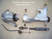
When the ParaLever was removed and I began seeing the hidden craftsmanship and innovative thinking that went into those parts of my bike as I handled each one:
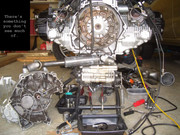
Removing the Transmission--
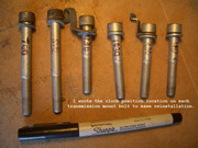
In removing the tranny-to-engine bolts you need to identify each one's location as you remove them, like this:
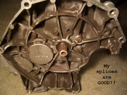
Without further delay I installed the 2 (homemade) transmission guide pins into the dowel holes at the 10:30 and 5:00 O'Clock bellhousing positions, then supporting the tranny so it was axial and seen as weightlees by the clutch hub splines, removed
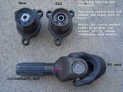
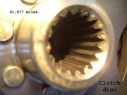
The first thing I checked was the cruddy looking splines and they looked good for the 61K miles
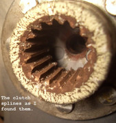
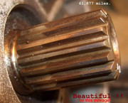
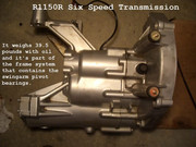
After cleaning and greasing the splines with Honda 60 Moly paste which is meant for splines on shaft drive Hondas, I reinstalled the transmission. It slid into place the first try so easy that it surprised me. Good alignment, slow movement and patience are required for this job and I cautiously used it all handling the 39.5 pound transmission (17.9Kg) all by myself. I expected a nightmare in trying to turn the shaft for spline alignment while trying to manoeuvre the heavy transmission, but it was not necessary. The next time you (or I) do this job it should get the very waxy, stiffer, hard to remove, weather and heat resistant BMW grease specified in the manual. It's also specified for use on the clutch/brake lever pivots too. Then the bolts with their attached washers and brackets were needed, using their Clock I.D. names for where they go.
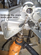
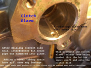
--Adding Slave Drain Line--
Finally, after the swing arm was off I was able to implement plans I had from long ago to install a drain pipe in the lower slave cylinder chamber. I got creative and modified the transmission case so the mod is permanent -and- to the unknowing it will appear as an OEM feature. Since the space between the 2 components is thin, I had to dig a drainage ditch on the bottom inside surface to the pipe's inlet. I routed the clear tubing connected to the new brass spigot down and forward, under the shifter, adjacent to the oil cooler return line. That gives me a discrete but visible indicator of a gearbox seal or slave piston seal leak -and- what the liquid smells like will tell me which one it is. No big deal to make, no safety or reliability negatives and one of the better do-as-I-go mods I'm most proud of:
--Clutch Master Cylinder--
I also took apart the clutch master cylinder to totally clean it out for it's 2nd life with the new slave assembly. Do NOT use brake cleaner solutions on the rubber parts, use new DOT4 fluid and a tooth brush. Putting it back together was "difficult" because of precise alignment of the internal snapring's tab (seen at the 7 O`Clock position in the pic) into a slot in the master cylinder's bore, against strong internal spring pressure. Look for the tab's slot in the MC bore so you know how to initially align it.
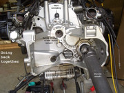
--Going Back Together--
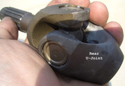
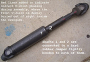
You need to put the U-Joints in phase, where the inner Yokes holding the needle bearings perfectly align with each other. Because the splines are so coarse, you should be able to get it right just eye-balling it. Then the drive shaft needs to be installed onto the transmission shaft splines until it bottoms out. To make it pop over the internal retaining circlip, drive it home by swinging the drive shaft sideways to expose one of the transmission's U-Joint Yoke's forged bearing frame so you can hit it with a hard forward tap using a large rubber or dead-blow plastic mallet. You should hear the click at the tranny output shaft when you do. To test if it did engage, try removing the drive shaft by hand.
Next the large end of the smaller rubber boot still on the swing arm front gets inserted over the drive shaft then carefully aligning and inserting the 2 front pivot bolts. Be careful the FD U-Joint does not fall off the drive shaft while setting the pivot pin free play or you'll loose the U-Joint phasing and have to remove the swingarm for visual access. Once the front pin locknuts are snugged up but not torqued yet, install the FD assembly and
their 2 pivot pins after Cleaning/WheelBearingGreasing the inner race shaft and caged needles. Adjusting the pivot bolts and torquing the locknuts may have to wait for the rear shock and torque arm installations if you cannot restrain the swingarm or FD's serious torque reaction when the locknuts are torqued.
--Summation--
The turn-key completion took 2 more days as I fussed with re-routing wires, cables and hoses, cleaned up the exhaust system and took advantage of my unlimited free time to go as slow as I wanted with very carefully hooking everything back up. I also took apart the starter to grease the bendix shaft's spiral and motor shaft bushings again while it was off the engine. It made a difference with much quieter starting. I did NOT put the royal PITA, lawyered-up red loctite on the swingarm pivot pin threads. Believe me, if/when they loosen (they won't), you WILL notice it right away in the handling well before it is an actual danger. Besides, 118 ft-lbs on super fine Aluminum threads is practically "welded on".
BTW, dealing with the throttle junction box and the fast idle lever assembly really is a royal pain-in-the-ass if you don't immediately know the sequence of operations to remove and take them apart. Once I figured it out, I realized its minimum parts holding each other together was uniquely BMW and quite crafty. My text in the pics will help you, but patience with the correct moves is required!! Take it apart inside a large plastic bag so if/when the tiny detent ball pops out unexpectedly, you'll still have it. The next time I work on it . . . . it'll be such a breeze . . . . it'll be fun.
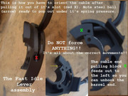
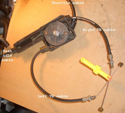
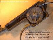
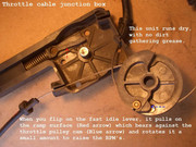
You do not have to remove the throttle junction box from the bike to lift the rear frame. You only have to disconnect the each cable at the TB's. I took the throttle junction box out and apart just to see how it was made and how the fast idle cam works. A very simple well made device with no apparent wobble inducing wear at the pulley pivot shaft or fast idle cam/ramp mechanism.
Overall, it was a satisfying, rewarding experience that gave me a new appreciation of some pretty clever designs and obviously high quality components . . . . like these:
Definitely NOT ANY great feelings for that $128 BMW dealer slave assembly and those input shaft spline design shortcomings
1st EDIT:
After speaking with Boxermania for almost an hour on the phone some good questions came up that were not answered or apparent in the pics. I chose an EDIT so it's all in one place.
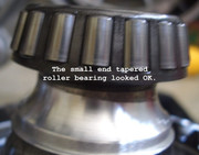
--What looked like burn or wear patterns on the FD tapered roller bearing roller and the outer race was actually just an oil film that wasn't yet wiped away.
--I did not remove the clutch disk for measurement or inspection because I knew the disc was nowhere near being worn out. My easy low RPM 1st gear engagements, frequent shifting without the clutch, no structural heat discolorations and an almost complete lack of dust residues in the bellhousing area reinforced my assumption the disk is still very reusable. Besides that, The "special" bolts have to be replaced if you remove them, torqued, then 32 degree angle tightened after that. I did not have the time, desire or extra costs of the "special" bolts and pilot shaft guide pin needed to deal with that. Planning on keeping this bike for another 2 years, when it'll be re-greasing and replacement time for the disc with the longer clutch hub.
--What looked like rust in the swingarm pivot roller bearings was just grease residues.
--Because I can easily take the FD apart again, the big shaft seal was cleaned, closely inspected, greased and reused.
--Yes, the FD tooth wear patterns were good ones.
--Do not treat the clutch slave as a lifetime part. In my estimation, it has a service life almost equivalent to a fuel filter that is never replaced.
2nd Edit:
--If you attempt this job in the continental USA, I can give you some preliminary or even in-a-jam do-as-we-go pointers over smartphones. PM me for my iPhone number (FaceTime?) and we'll take it from there. Especially you guys in Canada/UK/Europe/AussieLand!
.